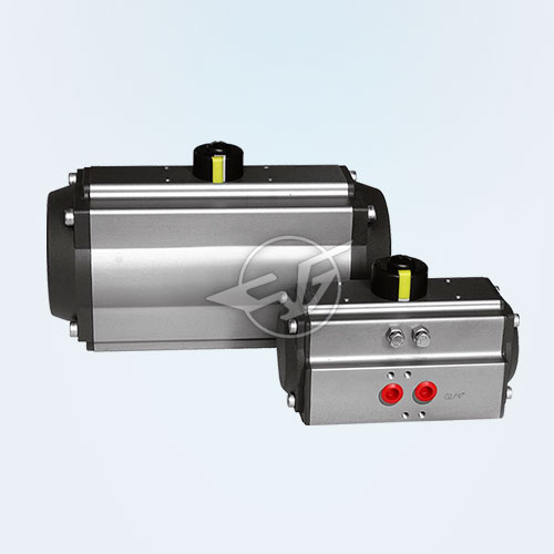
AT pneumatic actuator

Travel range: 0-90 degrees
Protection: IP67
Control: double-acting, single acting normally closed, normally open Single-acting
Configuration mode: rack and pinion piston
Can be equipped with valves: butterfly valves, ball valves, damper
Surface treatment: hard anode of the oxygen electrode
Can be equipped with accessories: a solenoid valve, an air filter regulator, s back, a hand wheel, electric positioner
First, the AT pneumatic actuator Product Overview
AT new rack and pinion pneumatic actuator combines the latest
technology at home and abroad, through CAD three-dimensional model
innovation and design, compact appearance, modern styling; and the use
of new materials, new technology, Product quality, more reliable
performance; more selection of more affordable specifications; products
fully meet the latest international standards and technical
specifications to meet current and future needs.
Second, the AT pneumatic actuator Features
1, double-piston rack and pinion symmetrical structure design, fast
and smooth movements, high precision, high output power, by simply
changing the piston assembly position can be obtained in the opposite
direction of rotation.
2, Extruded high-quality aluminum alloy cylinder body, hard-anodized
(in special case, anodized + Teflon coating) with precision machined
bore hole and external surface, longer service life and lower friction
coefficient.
3, one-piece design, all double-acting and single-acting actuator
models, have the same cylinder block and end cover, it is convenient by
adding spring or remove the spring to change the mode of action.
4, combined pre-charged safety spring group, either in the assembly
process or the use of the scene, can be convenient and safe installation
or increase or decrease the number of springs.
5, two separate side of the external adjustment screw has been
installed on the valve actuator is more precise and convenient, open and
valve control valve position, if the need for full stroke adjustment
while the other end cap is also equipped with a longer adjustment screw
.
6, Multi-function position indicator, visual indication on site, acc.
To VID / VIE3845, NAMUR standard slot, can install and output all
accessories, such as limit switch box, electrical positioner and
position sensor (Beckhoff, Turck).
7, Gas source interface with NRMAR standard, can be directly installed NUMAR standard solenoid valve.
8, the back of the rack of composite materials bearing and piston ring
and the output shaft bearings, etc. In order to prevent metal to metal
friction, and increase lubrication, so that low friction and long life.
9, all fasteners are made of stainless steel, long-term anti-corrosion.
10, the connection part of the line with the new international
standard ISO5211, DIN3337 (F03-F25) to make production and installation
of interchangeability, versatility.
Third, the double-acting principle (ATD)

CCW:
Air intake at port A. Compressed air overcomes spring force. Piston
outward movement, the actuator output shaft counterclockwise rotation (0
° → 90 °), B port exhaust;
actuator out of breath, the piston moves inward under the spring
force, the actuator output shaft clockwise 90 ° → 0 °), A mouth
exhaust.
CW:
A port inlet, compressed air to overcome the spring force to promote
outward movement of the piston, the actuator output shaft clockwise
rotation (0 ° → 90 °), B port exhaust;
actuator vapors. Pistons in the spring force The actuator output shaft
rotates counterclockwise (90 ° → 0 °) and the A port exhausts.
Fourth, single-acting working principle (ATE)

CCW:
A port inlet, compressed air to promote the piston outward movement of
the actuator output shaft counterclockwise rotation (0 ° → 90 °), B
port exhaust.
B port intake, compressed air to promote piston inward movement, so
that the actuator output shaft clockwise (90 ° → 0 °), A exhaust port.
CW:
A port inlet, compressed air to promote the piston outward movement,
so that the actuator output shaft clockwise (0 ° → 90 °), B exhaust
port.
B port intake, compressed air to promote piston inward
movement, so that the actuator output shaft counterclockwise rotation
(90 ° → 0 °), A exhaust port.
Five, AT pneumatic actuator technical parameters

| Technical Parameters | |||
| Components | Corrosion level | ||
| A | B | ||
| Cylinder | Anode hardened | Hand-operated mechanism can be manually open, close the valve | |
| End cap | Metallic polyester coating | Teflon coating | |
| Output shaft | Carbon steel electroless nickel plating | Carbon steel Electroless nickel or stainless steel | |
| Use the occasion | General occasion | General occasions or low concentrations of acidic environment | |
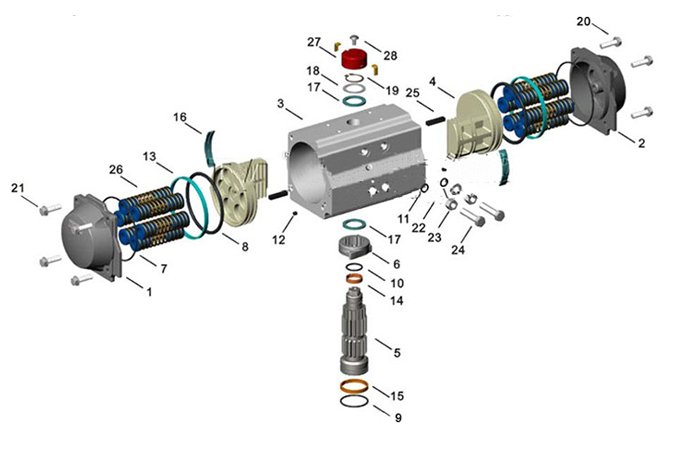
| Anatomical figure parameters | ||||
| Part Number | Each number | Part Name | Standard material | Selection of materials |
| 01 | 1 (1) | Left end cover | Die-cast aluminum | stainless steel |
| 02 | 1 (1) | Left end cover | Die-cast aluminum | stainless steel |
| 03 | 1 | Cylinder | Extruded aluminum alloy | stainless steel |
| 04 | 2 | piston | Die-cast aluminum | - |
| 05 | 1 | Output shaft | Carbon steel | stainless steel |
| 06 | 1 | Adjust the cam | stainless steel | - |
| 07 | 2 | O-ring (end cap) | Nitrile rubber | Fluorine or silicone rubber |
| 08 | 2 | O-ring (piston) | Nitrile rubber | Fluorine or silicone rubber |
| 09 | 1 | O-ring (bottom of output shaft) | Nitrile rubber | Fluorine or silicone rubber |
| 10 | 1 | O-ring (top of output shaft) | Nitrile rubber | Fluorine or silicone rubber |
| 11 | 2 | O-ring (adjusting bolt) | Nitrile rubber | Fluorine or silicone rubber |
| 12 | 2 | Plug (cylinder) | Nitrile rubber | Fluorine or silicone rubber |
| 13 | 2 | Bearing (piston) | Fluorocarbon composite materials | - |
| 14 | 1 | Bearing (top of output shaft) | Nylon 46 | - |
| 15 | 1 | Bearing (top of output shaft) | Nylon 46 | - |
| 16 | 1 | Bearing (back of piston) | Nylon 46 | - |
| 17 | 2 | Thrust bearings (output shaft) | Nylon 46 | - |
| 18 | 2 | Gasket (output shaft) | Nylon 46 | - |
| 19 | 1 | Elastic file circle | stainless steel | - |
| 20 | 8/12/16 (2) | End cap bolts | stainless steel | - |
| twenty one | 8/12/16 (2) | End cap gasket | stainless steel | - |
| 22 | 2 | Gasket | stainless steel | - |
| twenty three | 2 | Nuts | stainless steel | - |
| 24 | 2 | Adjustment bolt | stainless steel | - |
| 25 | 2 | Guide block | Nylon 66 + 30% FG | - |
| 26 | 5-12 | Spring assembly | Alloy spring steel | - |
| 27 | 1 | Location indicator | Polypropylene PP + 30% FG |
- |
| 28 | 1 | Screw | stainless steel | - |
| Shape and connection dimensions (mm) | ||||||||||||||
| model | AT50 | AT63 | AT75 | AT88 | AT100 | AT115 | AT125 | AT145 | AT160 | AT180 | AT200 | AT240 | AT265 | AT330 |
| D / E | ||||||||||||||
| ISO flange | F04 | F05 | F05-07 | F05-07 | F07-10 | F07-10 | F07-10 | F10-12 | F10-12 | F12 | F14 | F16 | F16 | F16 |
| A | 140.5 | 158.5 | 210.5 | 247.5 | 268.5 | 315 | 345 | 408.5 | 437.5 | 487 | 546 | 633 | 728 | 876 |
| B | 26.5 | 30 | 30.5 | 32.5 | 37.5 | 42.5 | 45 | 47.5 | 52 | 58.5 | 62.5 | 78.5 | 165 | 187 |
| C | 20 | 20 | 20 | 20 | 20 | 30 | 30 | 30 | 30 | 50 | 50 | 50 | 50 | 50 |
| φD | 40 | 40 | 40 | 40 | 40 | 56 | 56 | 65 | 65 | 80 | 80 | 115 | 115 | 115 |
| E | 59 | 72 | 84.5 | 97.5 | 111 | 127 | 136 | 156.5 | 169 | 190.5 | 213 | 251 | 298.5 | 383 |
| F | 69 | 85 | 102 | 115 | 127 | 145 | 157 | 177 | 196 | 220.5 | 245 | 298.5 | 330 | 405 |
| G | 29 | 36 | 42.5 | 49.5 | 56 | 64 | 69.5 | 80 | 88 | 99 | 110 | 131 | 163.5 | 201 |
| H | 41.5 | 47 | 52 | 56.8 | 67 | 77 | 82 | 91.5 | 99 | 105 | 112 | 131 | 166 | 204.5 |
| I | 14.5 | 14.5 | 14.5 | 14.5 | 14.5 | 24.5 | 24.5 | 24.5 | 24.5 | 44.5 | 44.5 | 44.5 | 44.5 | 44.5 |
| J min | 12 | 16 | 16 | 19 | 19 | 24 | 24 | 29 | 29 | 29 | 38 | 38 | 48 | 57 |
| k | 11 | 11 | 17 | 17 | 17 | 27 | 27 | 27 | 27 | 36 | 36 | 36 | 36 | 36 |
| L | 80 | 80 | 80 | 80 | 80 | 80 | 80 | 80 | 80 | 130 | 130 | 130 | 130 | 130 |
| M | 30 | 30 | 30 | 30 | 30 | 30 | 30 | 30 | 30 | 30 | 30 | 30 | 30 | 30 |
| N | 4 | 8 | 8 | 8 | 8 | 8 | 8 | 8 | 8 | 8 | 8 | 8 | 8 | 8 |
| EO1 | 42 | 50 | 50 | 50 | 70 | 70 | 70 | 102 | 102 | 125 | 140 | 165 | 165 | 165 |
| EO | - | - | 70 | 70 | 102 | 102 | 102 | 125 | 125 | - | - | - | - | - |
| P1 | 4-M6 | 4-M6 | 4-M6 | 4-M6 | 4-M8 | 4-M8 | 4-M8 | 4-M10 | 4-M10 | 4-M12 | 4-M16 | 4-M20 | 4-M20 | 4-M20 |
| P | - | - | 4-M8 | 4-M8 | 4-M10 | 4-M10 | 4-M10 | 4-M12 | 4-M12 | - | - | - | - | - |
| Q | 11 | 14 | 14 | 17 | 17 | 22 | 22 | 27 | 27 | 27 | 36 | 36 | 46 | 55 |
| V | 24 | 24 | 24 | 24 | 24 | 24 | 24 | 24 | 24 | 24 | 24 | 40 | 40 | 40 |
| W | 32 | 32 | 32 | 32 | 32 | 32.9 | 32 | 32 | 32 | 32 | 32 | 45 | 45 | 45 |
| Y. | M5x8 | M5x8 | M5x8 | M5x8 | M5x8 | M5x8 | M5x8 | M5x8 | M5x8 | M5x8 | M5x8 | M6x10 | M6x10 | M6x10 |
| Z | 1/8 " | 1/8 " | 1/8 " | 1/8 " | 1/4 " | 1/4 " | 1/4 " | 1/4 " | 1/4 " | 1/4 " | 1/4 " | 3/8 " | 1/2 " | 1/2 " |


 No.31011802002466

